Stop Buying Expensive Power Testers and Start Using V-I Plots
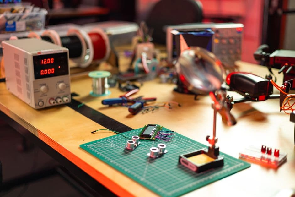
Ditch the pricey automated diagnostic tools. Learning to interpret V-I curves using a basic oscilloscope is the most reliable way to troubleshoot board-level failures.
Most hardware diagnostic tools are glorified black boxes. You plug in a board, it flashes a green light if things are okay or a red light if they aren't, and you are left wondering what actually died. If you are serious about fixing electronics, you need to stop relying on these automated testers and start looking at the actual current-voltage relationship. This is called a V-I plot, and you probably already have the gear to pull it off.
What is a V-I Plot?
At its core, a V-I curve is just a graph of voltage versus current. When you apply a sweep of voltage across a component and measure how much current flows, you get a unique "fingerprint." A resistor gives you a straight line. A diode gives you that classic hockey-stick shape. A complex integrated circuit gives you a chaotic, beautiful, and highly specific mess of lines that represents its health.
When you have a known-good board sitting next to the broken one, comparing their V-I plots is the fastest way to spot a short, an open circuit, or a component that is leaking current. It is essentially comparing two ECGs for a motherboard.
Why Automated Testers Fail You
The market is flooded with power testers that promise to identify bad rails or faulty power delivery chips. These devices often perform a simple resistance check or a voltage check while the device is powered. If you are lucky, they give you a code.
The problem, as noted by Tektronix, is that these automated checks only look for binary pass/fail states. They rarely capture the subtleties of a component that is failing under load or a trace that has degraded. A V-I plot, however, shows you the behavior of the entire circuit. If a capacitor is starting to fail but hasn't fully shorted, a multimeter might show a normal resistance, but a V-I curve will show a distinct change in the slope of the trace compared to a healthy board.
Setting Up Your Own Curve Tracer
You do not need a dedicated, rack-mounted curve tracer from the 1980s that costs a fortune on eBay. You need a function generator and an oscilloscope.
- The Function Generator: Set this to a low-frequency sine wave—something around 60Hz to 100Hz works well.
- The Series Resistor: Place a resistor in series with the device you are testing. This limits the current so you don't fry the board while you are poking around.
- The Oscilloscope: Switch your scope to X-Y mode. Connect the X-axis to the voltage across the component and the Y-axis to the voltage across the series resistor.
Because the voltage across the resistor is directly proportional to the current flowing through the circuit (thanks to Ohm’s Law, as explained by All About Circuits), your screen is now plotting V versus I.
Why This Skill Matters
There is a tactile satisfaction in manually probing a board that automated testing simply lacks. When I am hunting for a dead MOSFET on a motherboard, I don’t want a screen telling me "Power Rail Error 4." I want to see the curve. I want to see the exact moment where the trace shifts, indicating the gate is stuck or the junction has broken down.
Learning to read these plots takes time, but it builds a "gut feeling" for electronics that no piece of automated software can provide. You start to recognize the signature of healthy CMOS inputs, the specific loop of a ceramic capacitor, and the jagged edges of a dying voltage regulator.
The Boring Truth About Diagnostic Gear
I see a lot of enthusiasts spending money on "smart" diagnostic dongles that promise to fix their PC or phone. These tools are often limited by their internal programming; they can only find the problems their developers anticipated. V-I plotting is universal. It doesn't care if the component is from a laptop, a vintage radio, or a server board. It simply shows you the physics of what is happening under the hood.
This is the boring, reliable path. It requires you to know how to use an oscilloscope, it requires you to understand how to interpret a graph, and it requires you to actually look at the hardware. But once you have that proficiency, you will find that those expensive "smart" testers end up sitting on a shelf collecting dust. You won't need them anymore because you will have the ability to see the truth of the circuit for yourself.